Dpls2 Wiring Diagram
Keep all wire connections above the highest water level. This is the diagram below to learn all the pin terminals of a double pole double throw (dpdt) relay:

6es7322 1bh01 0aa0 Wiring Diagram
Onsite wiring may be different from that shown.
Dpls2 wiring diagram. These harnesses include the gen ii lt1/lt4, gen iii (24x) ls1/ls6 and vortec truck engines as well as gen iv (58x) ls2, ls3, ls7, & vortec and gen v lt / ecotec3 engines. It shows how the electrical wires are interconnected and can also show where fixtures and components may be connected to the system. We're going to connect a double pole double throw relay to a circuit to light up leds.
Premium color wiring diagrams get premium wiring diagrams that are available for your vehicle that are accessible online right now, purchase full set of complete wiring diagrams so you can have full online access to everything you need including premium wiring diagrams, fuse and component locations, repair information, factory recall information and even tsb's (technical. The 2 coil terminals is where the voltage is placed in order to energize the coil. The three phases are then connected to a power interrupter.
This is the circuit below: Wiring diagram book a1 15 b1 b2 16 18 b3 a2 b1 b3 15 supply voltage 16 18 l m h 2 levels b2 l1 f u 1 460 v f u 2 l2 l3 gnd h1 h3 h2 h4 f u 3 x1a f u 4 f u 5 x2a r. Note that symbols are discussed in detail later).
Look at picture 1.1 and 1.2, it consists of two common input terminals c, e and both mechanically tied together to operate in the same way. When the relay is powered, the red led and the fan shut off and the green led and the dc motor turn on. The electrical wiring diagram is a pictorial representation of the circuit which shows the wiring between the parts or elements or equipment.
Proper installation of mitsubishi electric condensate pump on the m and p series. Wires must be joined with butt connectors and a marine grade sealant to prevent wire corrosion. An example of a wiring diagram for a motor controller is shown in figure 1.
Nabco factory utilizes underwriters laboratories (ul) recognized component wire, terminals and connector housings to manufacture opus automatic door systems. This drain pan level sensor provides automatic protection against condensate overflow in mitsubishi's mini split indoor units. If the sensor detects high levels of condensate building up in the drain pan, it will send a signal to the control box that shuts off the indoor unit until the drain pan is at a safe level, protecting your home and mini split system.
A wiring diagram is a simple visual representation of the physical connections and physical layout of an electrical system or circuit. Electrician circuit drawings and wiring diagrams youth explore trades skills 3 pictorial diagram. It's likely though, you've already read the wikipedia page about series and parallel circuits here, maybe a few other google search results on the subject and are still unclear or wanting more specific information as it pertains to leds.
Les fils doivent être raccordés avec des connecteurs bout à bout et un mastique marine When the relay isn't powered, both the red led and the dc fan are on,. Psi sells standalone wiring harnesses for gm gen ii, iii, iv, & v ls/lt based engines and transmissions.
Hopefully those looking for practical information on electrical circuits and wiring led components found this guide first. Connect the control box's splice connector to the mating connector on the wire harness (fig 1). This system uses 3 phase ac power (l1, l2 and l3) connected to the terminals.
The polarity of the voltage does not matter. All psi harnesses are made in the usa. All wiring diagrams included within this manual, reflect typical primary and secondary circuits that might be commonly used.
Fig 1.2 dpdt terminal diagram. Dashed lines indicate a single purchased component. Base diagram for high voltage wiring.
In this article, we are sharing the basic concepts of plc and dcs control systems wiring diagrams for digital input (di), digital output (do), analog input (ai), and analog output (ao) signals. The input supply always is given to the common terminal c and e only. Place the relay's rated coil voltage on these terminals.
Terminal a, b, d, and f are the output terminal and which will be connected to the outside circuit.
Freightliner TCM/wiring harness question Pirate 4x4
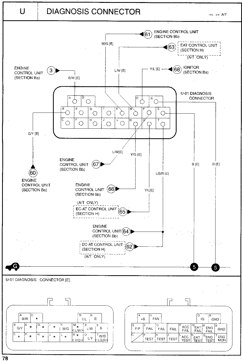
Wiring on an OBD2 Plug to your Kia FE3 [Fe3 Wiki]

Where Can I Find A Wiring Diagram For A Harbor Freight 7000/8750 Watt Gener... DIY Forums
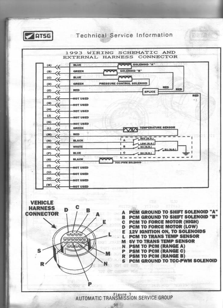
4L80E torque lockup problem Page 2

Wiring Diagram Of Motorcycle Honda Xrm 110 bookingritzcarlton.info, bookingritzcarltoninf
Any HVAC gurus on here? Looking for help with wiring a thermostat The Hull Truth Boating and
Just to confirm my Hive 2 receiver wiring is correct. DIYnot Forums
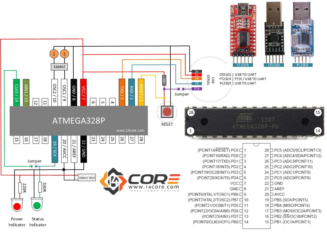
Wiring a Stand Alone ATMEGA328P CMOS 8Bit Microcontroller
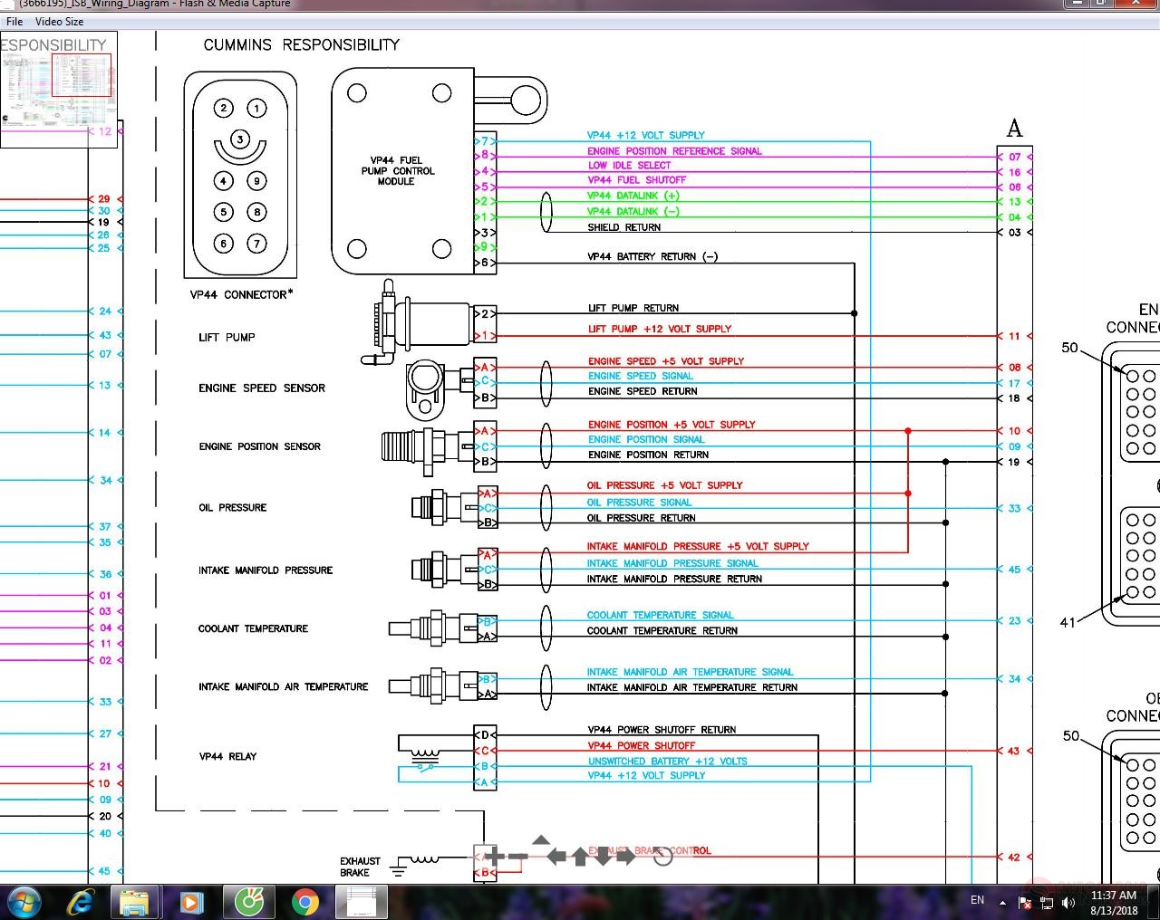
Cummins ISB 366619502 Wiring Diagram Auto Repair Manual Forum Heavy Equipment Forums

Schéma electrique fiat ulysse 2 boisecoconcept.fr

1987 KTM 250 MX wiring KTM Forums KTM Motorcycle Forum
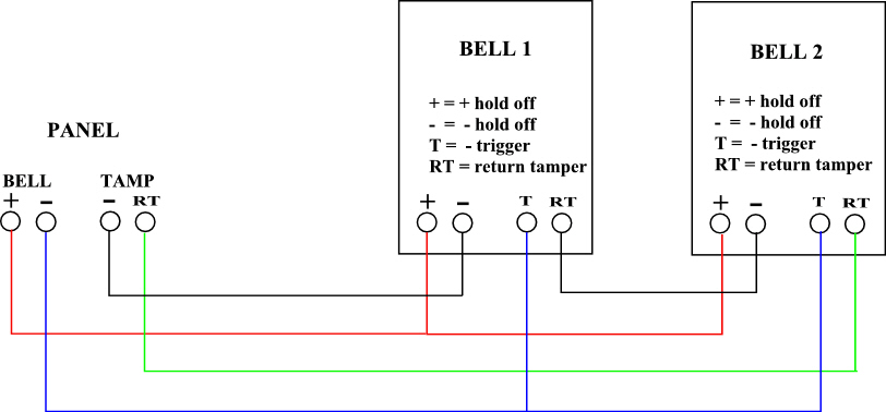
Honeywell Galaxy 212 Wiring Help Needed !!..DIY Installers..!! Security Installer Community
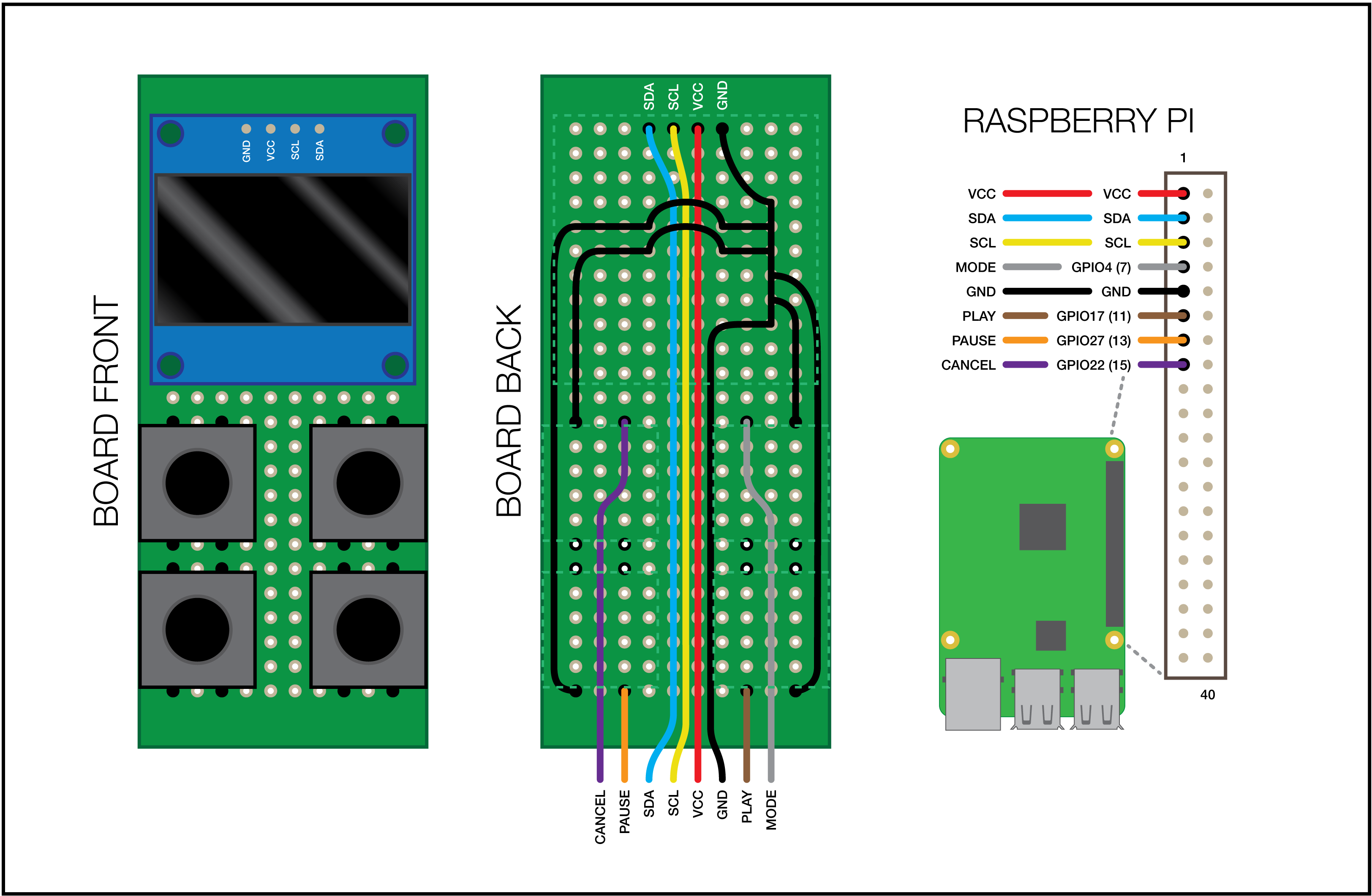
OctoPrint Micro Panel
Potterton Ep2000 to Ep2 change. DIYnot Forums
Isuzu Pickup 4×4 2.6L EFI 1990 Electrical Circuit Wiring Diagram » CarFuseBox
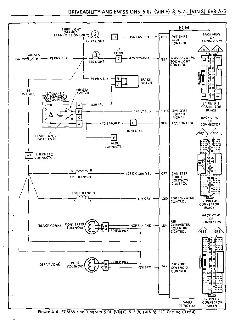
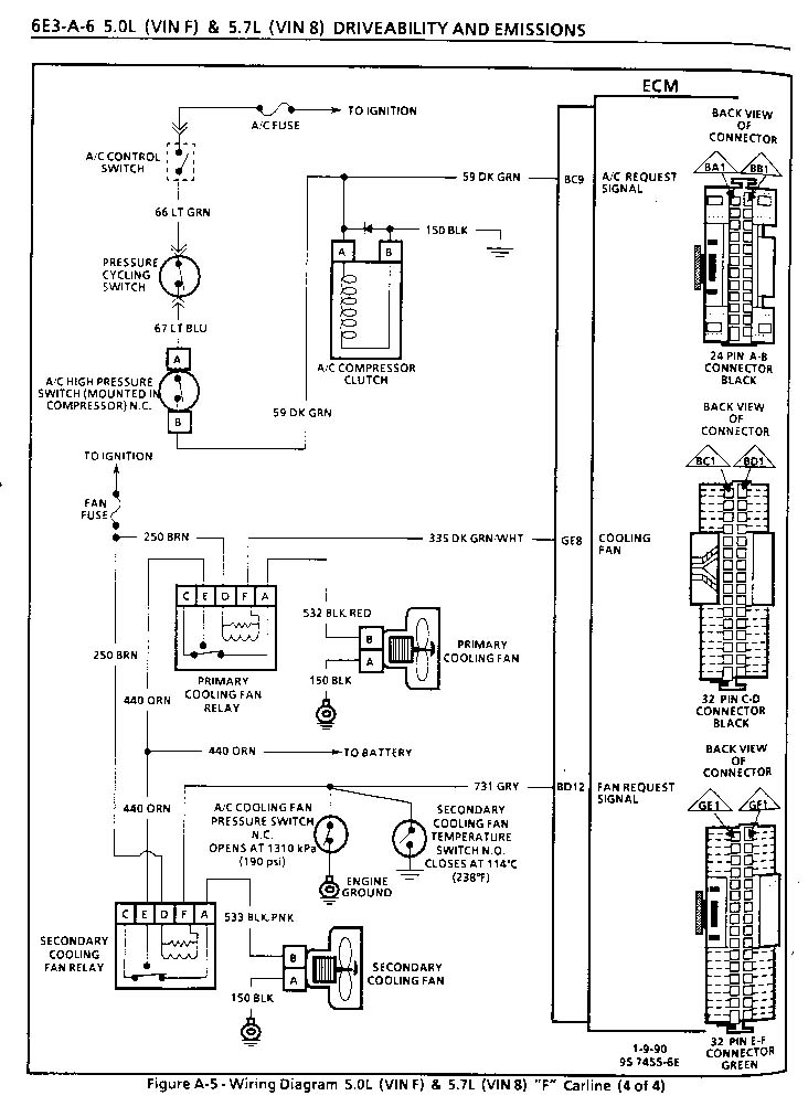
My 85 Z28 and Changing a '165 ECM to a '730
Installing Honeywell DT92E into Danfoss WB12 wiring box DIYnot Forums
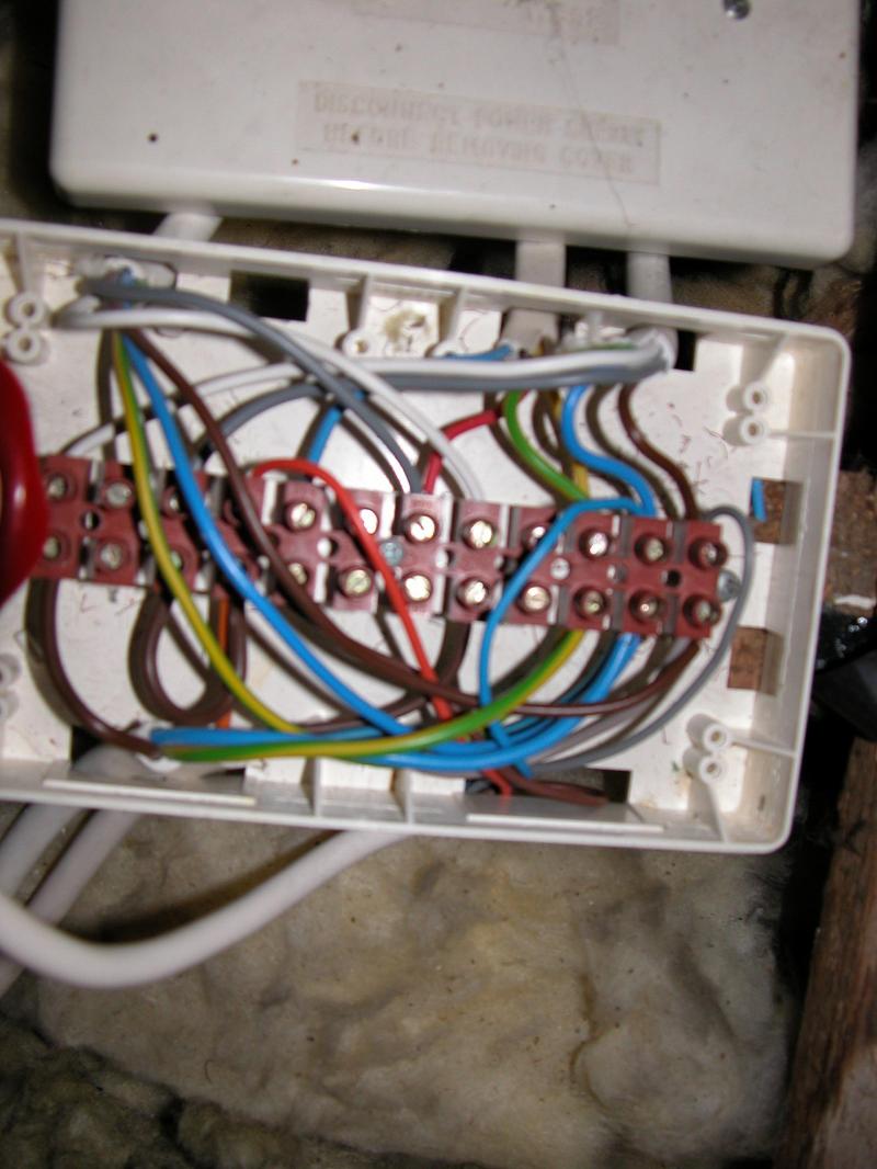
Hive and Potterton Titanium DIYnot Forums
My 85 Z28 and Changing a '165 ECM to a '730