1 Wire Gm Alternator Wiring Diagram

Rj11 Socket Wiring Diagram Australia, How to punch down an RJ11 Telephone Jack, 6.36 MB, 04:38, 387,634, CableSupply.com, 2009-08-05T00:16:07.000000Z, 19, Rj11 Socket Wiring Diagram Australia | Computacion, Redes de computadoras, Computadoras, www.pinterest.com.mx, 728 x 783, jpeg, rj11 wiring rj45 diagram cable ethernet usb jack pinout adapter cat5 female male convert using rs485 cat wires code socket, 20, rj11-socket-wiring-diagram-australia, Anime Arts
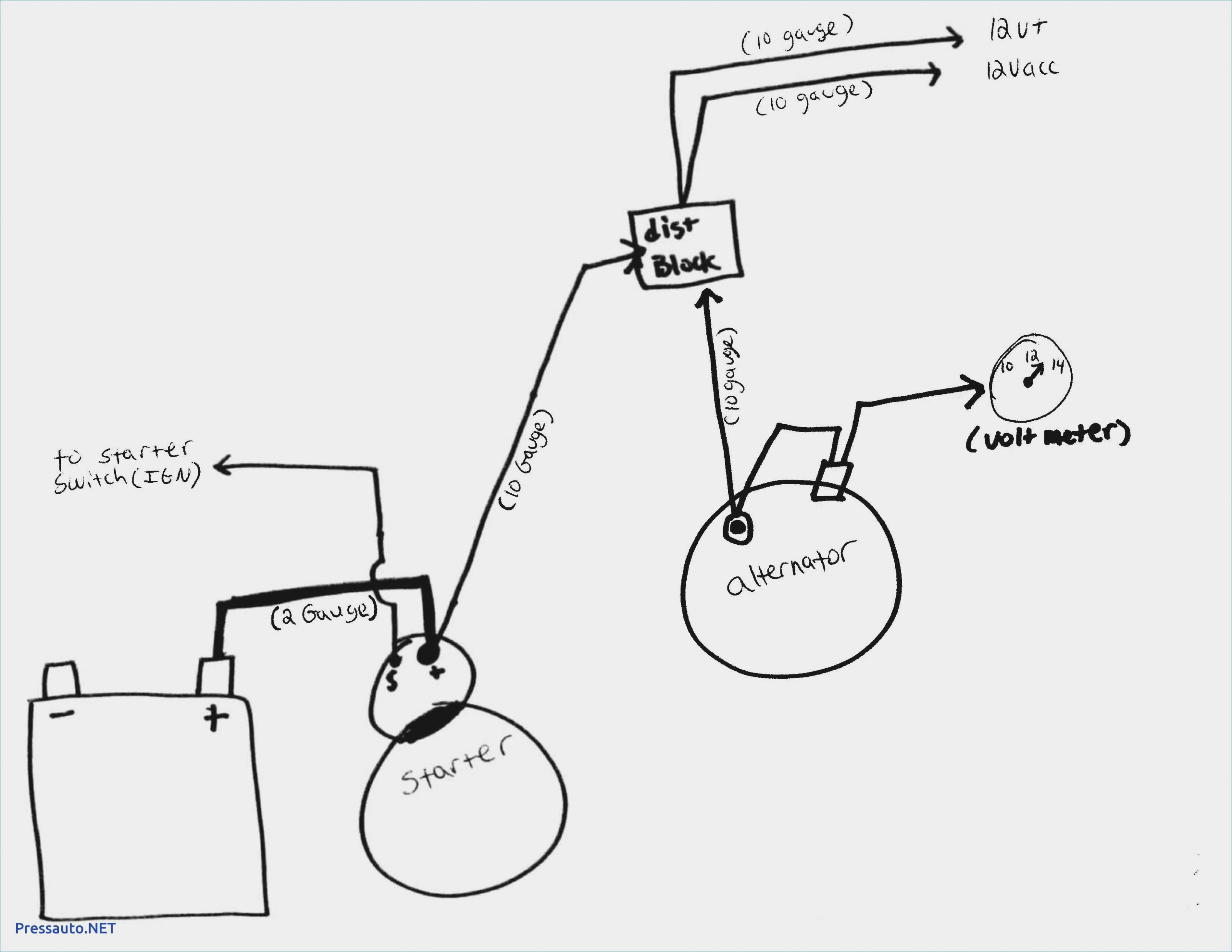
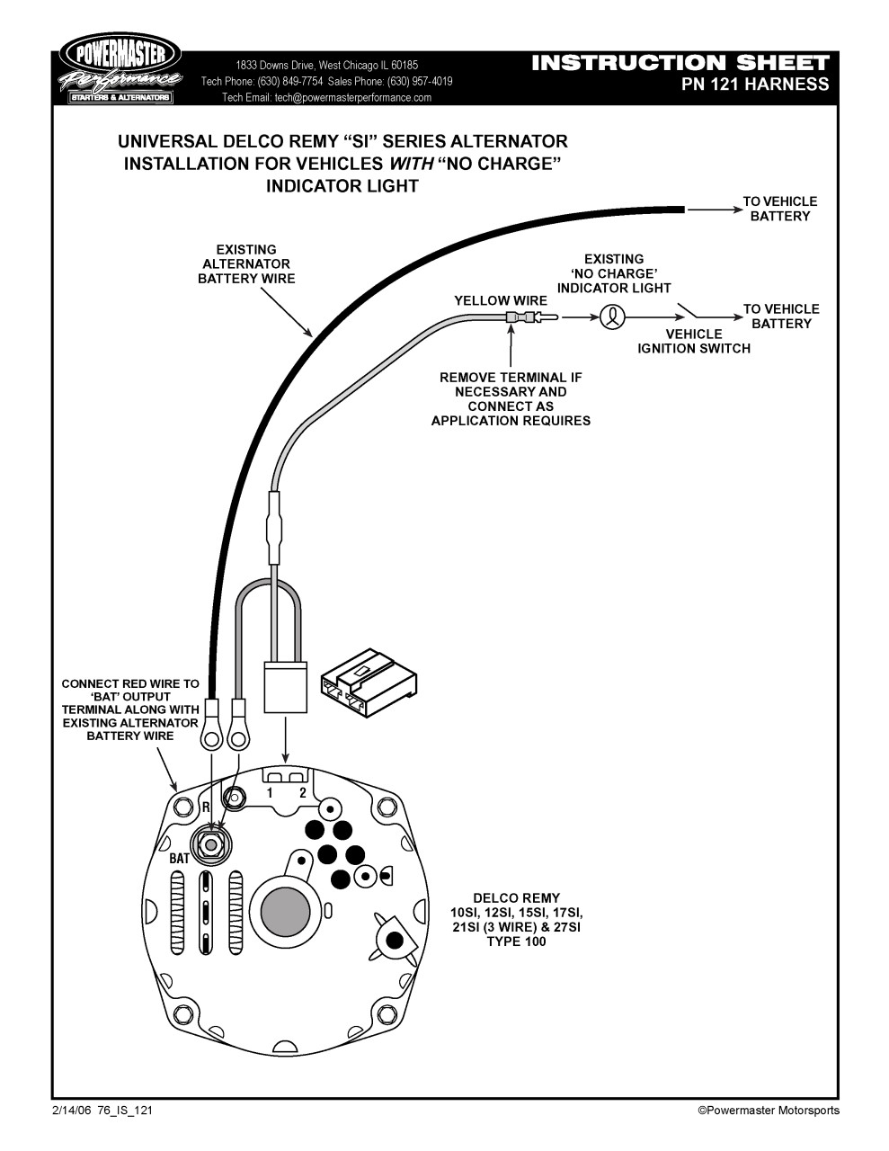
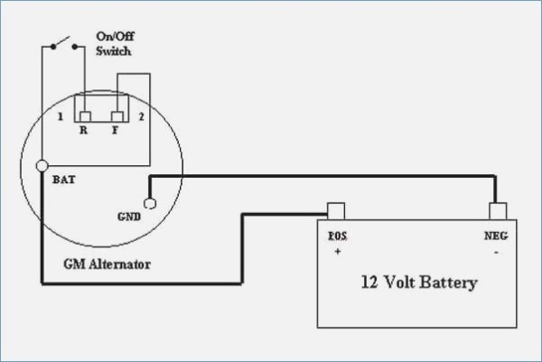
Then simply run one wire from the alternator 'battery' terminal to the positive terminal of the battery or to the starter solenoid main lug, which is connected to the positive battery post. Reconnect the positive battery cable, start the engine and using a vom meter, verify that the alternator is correct wire size is critical. The alternator turns on the voltage regulator when the engine starts turning the alternator. Two wire means that you use the main battery wire to the back of the alternator and also ignition wire to the #1 terminal to.
Here is a picture gallery about 1 wire alternator wiring diagram complete with the description of the image please find the image you need. Wiring diagram for a gm 3 wire alternator. 1 wire alternator wiring diagram. When theres a floor wire it will be a copper wire saved in place by a mess on the same side since the fairly neutral terminal. What are the 2 wires on an alternator. One wire is the power wire that goes to the positive terminal or the solenoid. While the second wire is the one that is connected to the harness and informs you about the battery level. In other words, this is the wire for the battery light that you see on the dash. Today i show you how to wire a 10si one wire/three wire alternator to a diesel farm tractor.
Gm 1 Wire Alternator Wiring Diagram - Cadician's Blog

Projects - '58 Delray | Page 2 | The H.A.M.B.
Gm 1 Wire Alternator Wiring Diagram : Catalog : And even searched in here (only found ford 4

Technical - Alternator install help/tips & suggestions/ | The H.A.M.B.
gm 1 wire alternator wiring diagram - Wiring Diagram
» GM 10SI/12SI Alternator Wiring - (1-Wire) - GM Alternator Diagrams - GM 10SI/12SI Alternator
Gm 1 Wire Alternator Wiring Diagram - Database - Wiring Diagram Sample

Single Wire Alternator Wiring Diagram

Gm 1 Wire Alternator Wiring Diagram - Database - Wiring Diagram Sample

1 Wire Alternator Diagram | Alternator, Car mechanic, Automotive mechanic
