Transducer Wiring Diagram

Rj11 Socket Wiring Diagram Australia, How to punch down an RJ11 Telephone Jack, 6.36 MB, 04:38, 387,634, CableSupply.com, 2009-08-05T00:16:07.000000Z, 19, Rj11 Socket Wiring Diagram Australia | Computacion, Redes de computadoras, Computadoras, www.pinterest.com.mx, 728 x 783, jpeg, rj11 wiring rj45 diagram cable ethernet usb jack pinout adapter cat5 female male convert using rs485 cat wires code socket, 20, rj11-socket-wiring-diagram-australia, Anime Arts
A beginner's guide to circuit diagrams. A first look at the circuit diagram may be confusing, in case look for a subway map, look for. Airmar's transducer cross reference offers a variety of transducer information—from wiring diagrams to sounder compatibility and more. Just enter the first few numbers of the part number and see the results immediately.
There are three kinds of electrical outputs used for this type of transducer like mv (mill volts), v (volts) & ma (current). The issues can be avoided by selecting the electrical output for a particular application as well as the wiring of the transducer for the type of electrical output. • pressure transducer exhibits an output at zero pressure (large zero offset). Refer to the wiring diagrams on the reverse for the ip rating of the unit which is being installed. Mounting the g2, g3, gv and t2 transducers require no special. 3 wire pressure transducer wiring diagram from i. ytimg. com to properly read a electrical wiring diagram, one provides to know how the particular components in the method operate. For example , if a module will be powered up and it sends out the signal of fifty percent the voltage in addition to the technician will not know this, he would think he has a problem, as he or she. A pressure transmitter is an analog device and is therefore connected to a plc analog input module. Many people refer to this device as a transducer.
Pressure Transducer Wiring Diagram | Free Wiring Diagram

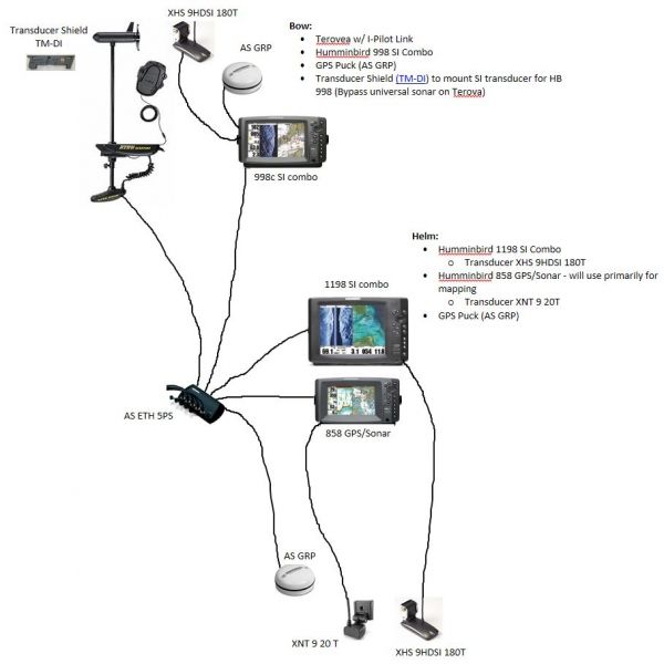
Humminbird Transducer Wiring Diagram

Airmar B60 Transducer Wiring Diagram - Wiring Diagram

Humminbird Piranha 20 Transducer Wiring Diagram

Garmin 6 Pin Transducer Wiring Diagram

Garmin Transducer Wiring Diagram

Garmin 8 Pin Transducer Wiring Diagram

Transducer discussion | Page 2 | Shamrock Boat Owners' Club
Garmin 6 Pin Transducer Wiring Diagram

4 20ma Pressure Transducer Wiring Diagram | Free Wiring Diagram
